9.6 DESIGN OF GIMBAL MOUNTS
Gimbal Design Considerations
Primary design considerations for gimbal mounts are:
- Required pivotal movement of engine assembly or thrust chamber for thrust vector con-trol.-Generally ranging from to .
- Required adjustment for thrust alinement and positioning.
- Thrust level.-This determines the structural and bearing design of the gimbal mounts.
- Required operational life.-Generally 1000 cycles minimum.
- Minimum deformation of the bearing surface, prevention of bearing surface galling.
- Propellant duct installation.-Some designs require flow of one of the propellants through the center of the gimbal mount.
- Maintenance of the gimbal mount.-This is largely affected by the lubrication requirement of the bearing surfaces. If possible, a gimbal boot should be provided to protect the bearing surfaces from dust, water, and foreign materials.
- Lightweight.-High strength-to-weight materials should be used.
Ring-Type Gimbal Mounts
Figure 9-23 presents a typical gimbal mount designed for low-thrust, upper stage engine applications up to 20000 pounds. The design is a closed-yoke, flowthrough-ring-type gimbal, utilizing plain bearing pivot joints. This configuration provides for the main oxidizer duct to pass through the assembly in the longitudinal axis to the thrust chamber dome. The gimbal mount is designed to connect the vehicle main oxidizer
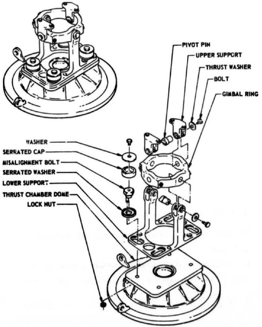 Figure 9-23.-Typical ring-type gimbal mount designed for low-thrust, upper stage engine applications.
duct and the top of the thrust chamber dome. The lower support of the gimbal mount provides an adjustment mechanism for thrust vector alinement. Except for the steel pivot pins and the alinement bolts, all other parts can be made of either aluminum or titanium alloys for minimum weight. The bearing surfaces of the pivot pins should be chromium or electroless nickel plated. Solid film dry lubricant coatings or grease may be applied to all bearing, surfaces. The design bearing pressure of this gimbal type is about 10000 psi of bearing projected area. The bearing coefficient of friction is around 0.08 .
Cross-Type Gimbal Mounts
Figure 9-24 presents the design of a typical cross-type gimbal mount used on medium thrust engines (up to 200000 lb ), such as shown in figure 9-1. Here, the gimbal mount secures the engine assembly to the vehicle thrust frame, and is mounted to thrust chamber dome and elbow assembly. It consists of a cross-shaped unit
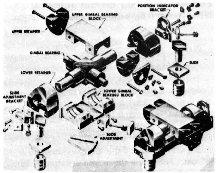 Figure 9-24.-Typical cross-type gimbal mount designed for medium-thrust engine applications.
incorporating bearing surfaces, upper and lower gimbal bearing blocks, upper and lower retainers, and thrust vector alining slides. All parts of this design are made of 4340 alloy steel. The bearing surfaces of the cross unit are chromium or electroless nickel plated. The bearing surraces are phosphate treated. Solid-film drylubricant coatings are applied to all bearing surfaces. The design bearing pressure of this type gimbal mount ranges from 15000 to 20000 psi of bearing projected area. The bearing coefficient of friction varies between 0.06 and 0.1 .
 Figure 9-25.-Typical socket-type gimbal mount designed for high-thrust engine applications.
Socket-Type Gimbal Mounts
Figure presents a typical heavy-duty gimbal mount designed for high-thrust engine applications (up to several million pounds). This mount is also designed to secure the engine assembly to the vehicle thrust structure. The unit consists of integral upper and lower bearing blocks, and their retaining bar. All parts are made of alloy steel. The thrust load is carried by a socket-type spherical bearing located between two bearing blocks. The surface of the spherical socket has a Teflon-fiber-glass com- position coating, which provides a dry, lowfriction bearing surface.
The bearing surface on the sphere is electroless nickel plated. No lubrication or maintenance is required. For these gimbal mounts, design bearing pressures range from 24000 to 28000 pounds per square inch of bearing projected area. The bearing coefficient of friction is about 0.15 .
Lateral adjustments for thrust alinement are accomplished using a tongue and groove arrangement between gimbal lower bearing block and thrust chamber dome.